Guidance Notes on Piling
Site Investigations, Site Preparation, Environment & Pile Performance
Site Investigations, Site Preparation, Environment & Pile Performance

Site Investigations
The investment in a professionally conducted site investigation will reduce the developer's risk. At project feasibility stage the viability of a development can be assessed.
Design parameters are obtained from the fieldwork and during subsequent laboratory testing. The better the information gained from the investigation, the more cost certainty can be ensured. With complete, reliable data at their disposal, the designer can offer economies.
Without a comprehensive site investigation, assumptions are made, conservatism will prevail and value engineering is impossible.
Who Should Carry Out the Work
An AGS (Association of Geotechnical & Geo-environmental Specialists) registered firm should be engaged to conduct the investigation, prepare the fieldwork schedule, commission the testing and report on the findings.
The laboratory work should be carried out by a suitably accredited laboratory. The report should be made in accordance with BS5930 (1999), and data supplied in AGS format.
What Methods Should Be Used
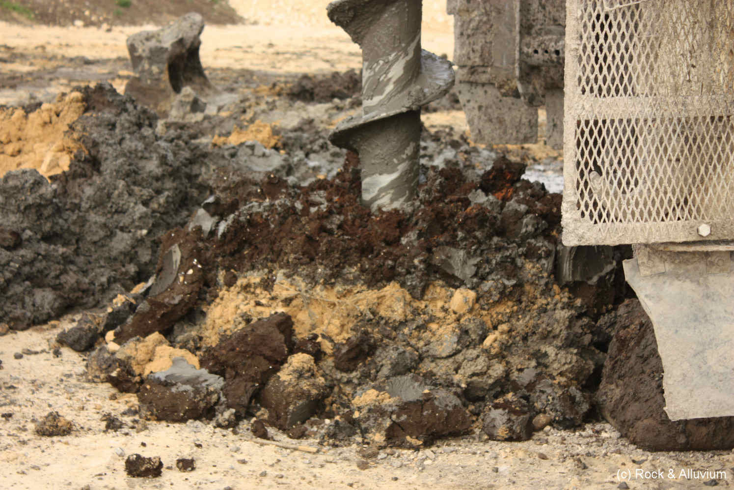
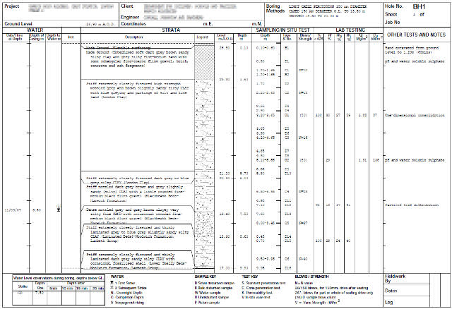
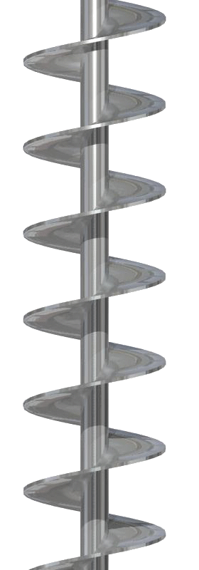
Shell & Auger boreholes are the most commonly adopted deep investigation technique. Consistency between the ground conditions encountered and those anticipated from geological references and between individual borehole locations should influence the extent of the works undertaken during the fieldwork phase.
Variability of ground conditions encountered may lead to alternative investigation techniques being considered. Trial pitting, window sampling, dynamic and cone penetrometer testing can all be used to supplement the information derived from shell & auger boreholes. Sulphate and pH testing should also be carried out on both soil and ground water samples. Appropriate testing should also be undertaken where contamination may be present.
Information obtained includes:
- Visual assessment
- Stratification
- Groundwater
- Bore instability
- Strength data
- Samples for laboratory testing
Other Considerations
 During U100 sampling, blow counts should be recorded in order that the designer has additional information at their disposal when assessing soil strength characteristics. Excessive blows during the sampling of hard clays can yield unreliable and low triaxial test results, which if presented alone can lead to an uneconomic design line.
Groundwater conditions must be accurately recorded. Blowing or piping in sands/gravels can cause low SPT results and the absence of accurate reporting can lead to an uneconomic design line. The addition of water during drilling can mask natural groundwater inflows therefore must be recorded in order that a correct assessment of soil densities can be made.
Should drilling refusal occur before the intended depth of the investigation has been reached, the actual nature of the refusal should be determined. It may be the case that bedrock stratum has been reached and the layer may be impenetrable by normal piling techniques. Rotary drilling may be required to prove the thickness of the layer. It is certainly the case that further boreholes should be installed on the site to check the consistency of the stratum encountered.
During U100 sampling, blow counts should be recorded in order that the designer has additional information at their disposal when assessing soil strength characteristics. Excessive blows during the sampling of hard clays can yield unreliable and low triaxial test results, which if presented alone can lead to an uneconomic design line.Groundwater conditions must be accurately recorded. Blowing or piping in sands/gravels can cause low SPT results and the absence of accurate reporting can lead to an uneconomic design line. The addition of water during drilling can mask natural groundwater inflows therefore must be recorded in order that a correct assessment of soil densities can be made.
Should drilling refusal occur before the intended depth of the investigation has been reached, the actual nature of the refusal should be determined. It may be the case that bedrock stratum has been reached and the layer may be impenetrable by normal piling techniques. Rotary drilling may be required to prove the thickness of the layer. It is certainly the case that further boreholes should be installed on the site to check the consistency of the stratum encountered.
Minimum Recommendations
| Soil Type | In-Situ | Laboratory |
|---|---|---|
| Clay | U100 followed by SPT at 1.5m intervals | Triaxial tests Moisture contents top 5m Soil Indicies |
| Sand Gravels | SPT at 1.5m intervals | Bulk densities |
| Weak Rock e.g. Chalk | SPT every 1.5m | Bulk densities |
Site Preparation
 Preparation of a construction site for piling requires more consideration and planning than may be first thought. Here we provide a brief outline of what our works involve and what we require from the Principal Contractor to achieve safe working conditions for our operatives, a cleaner site and improved production.
A properly prepared site will ensure a tidy safe working area as well as reducing time on your programme at an early stage. Please contact us if your require more information on Site Preparation for Piling.
Preparation of a construction site for piling requires more consideration and planning than may be first thought. Here we provide a brief outline of what our works involve and what we require from the Principal Contractor to achieve safe working conditions for our operatives, a cleaner site and improved production.A properly prepared site will ensure a tidy safe working area as well as reducing time on your programme at an early stage. Please contact us if your require more information on Site Preparation for Piling.
Piling Platform
 This is the working platform which the piling rig will need to track over and install the piles from. The platform is made up of appropriate material to carry a piling rig that will weigh over 30 tonnes.
Please see our Working Platform page for a copy of our Working Platform Certificate and the loadings each piling rig generates. There are also Working Platform requirements on the FPS Website.
Materials and Installation
Generally some form of reduced dig or grading of the ground surface along with the removal of underground obstructions and diversion of services is carried out prior to the platform being installed. Subject to the specific requirements of the working platform design, the platform would typically comprise a geotextile membrane laid on the prepared subgrade, then covered with granular material (particle size normally 75mm down to dust) laid to the thickness specified in the design.
Soft spots in the subgrade must be excavated and backfilled in compacted layers using granular fill. In certain situations platform thickness may be reduced through use of geo grid reinforcement.
The platform should overlay the footprint of the building plus a minimum of 2 metres all round. Access pathways are maintained, this will provide a safe environment for the piling rig and crew to work in.
This is the working platform which the piling rig will need to track over and install the piles from. The platform is made up of appropriate material to carry a piling rig that will weigh over 30 tonnes.Please see our Working Platform page for a copy of our Working Platform Certificate and the loadings each piling rig generates. There are also Working Platform requirements on the FPS Website.
Materials and Installation
Generally some form of reduced dig or grading of the ground surface along with the removal of underground obstructions and diversion of services is carried out prior to the platform being installed. Subject to the specific requirements of the working platform design, the platform would typically comprise a geotextile membrane laid on the prepared subgrade, then covered with granular material (particle size normally 75mm down to dust) laid to the thickness specified in the design.
Soft spots in the subgrade must be excavated and backfilled in compacted layers using granular fill. In certain situations platform thickness may be reduced through use of geo grid reinforcement.
The platform should overlay the footprint of the building plus a minimum of 2 metres all round. Access pathways are maintained, this will provide a safe environment for the piling rig and crew to work in.
Arrival on Site
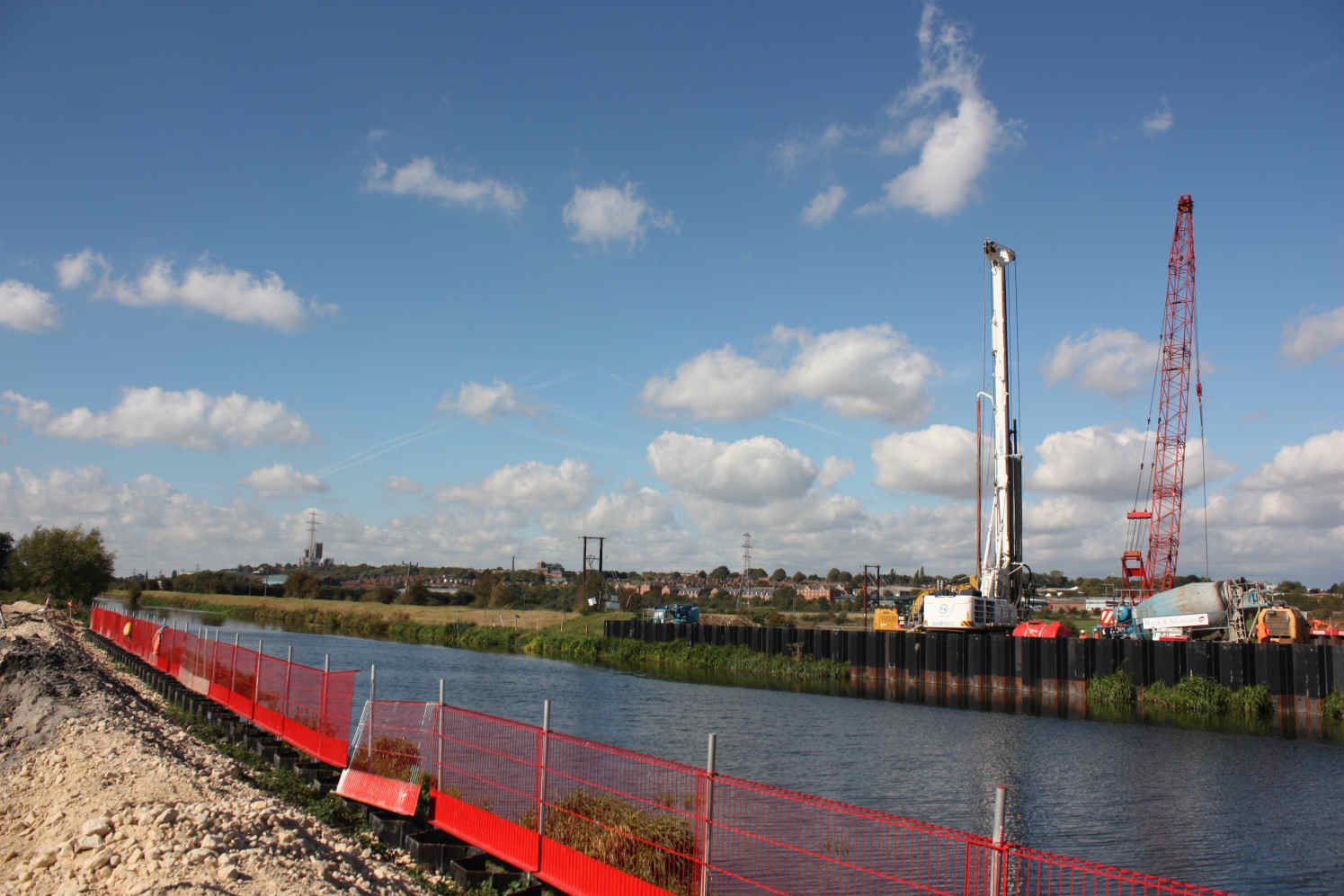
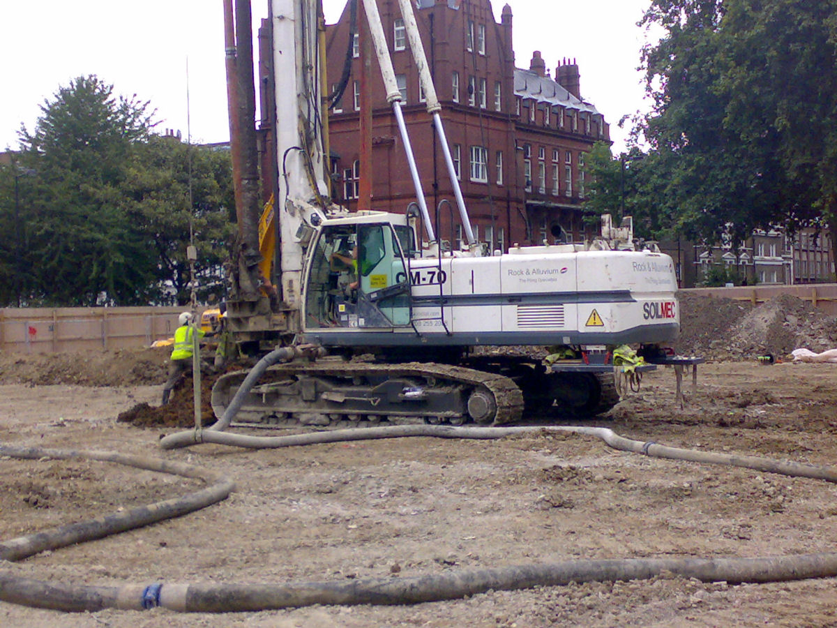
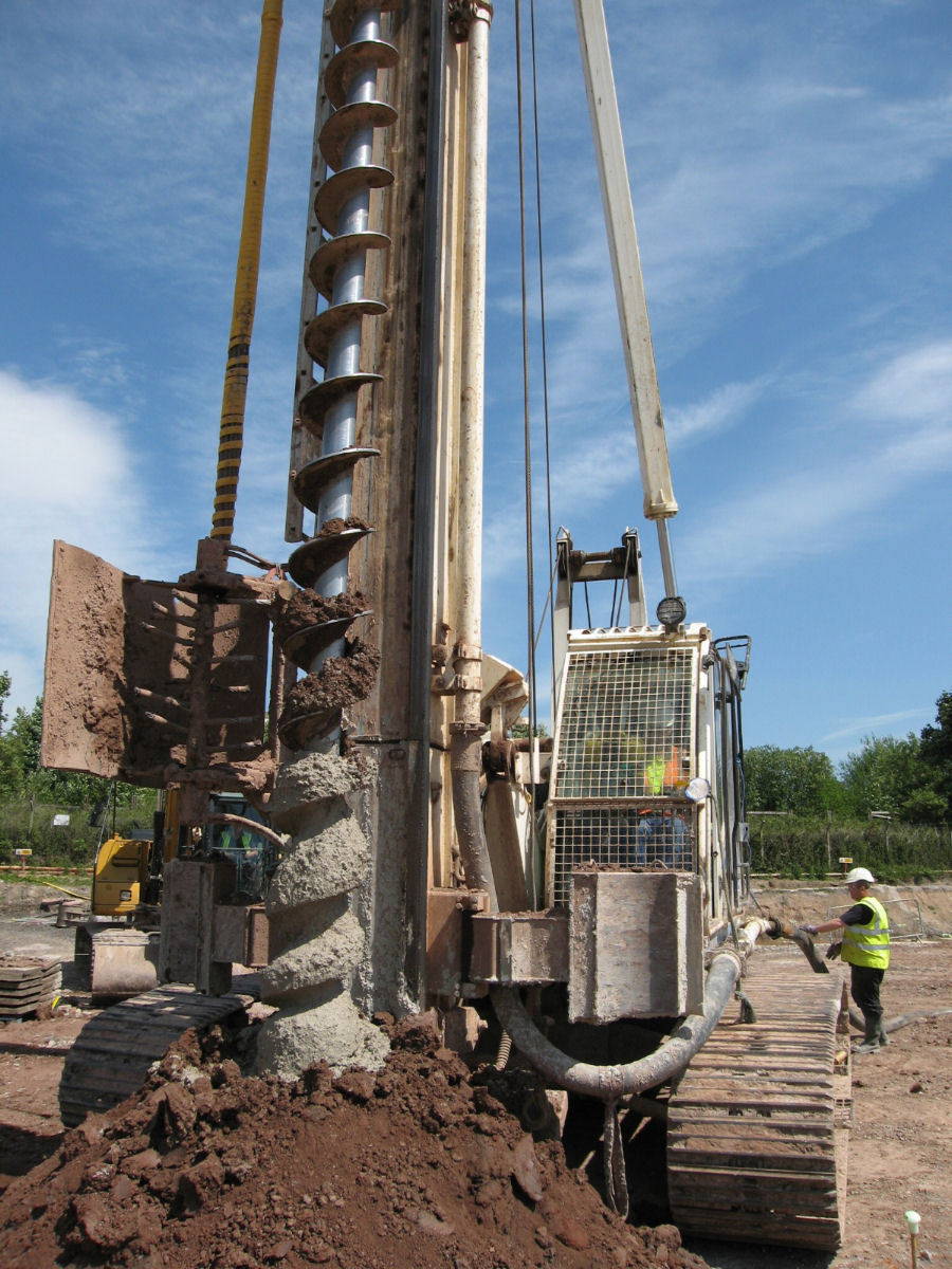
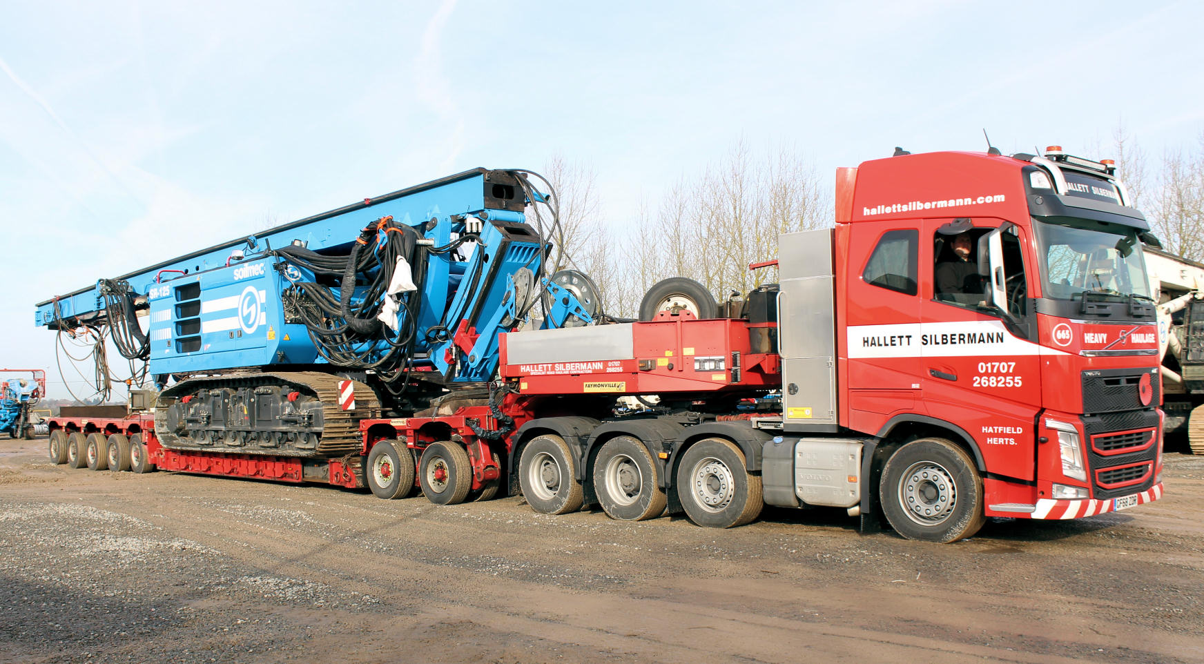 A piling rig is taller, wider and longer than most 360 degree excavators and has a variable center of gravity. Rigs are therefore not as manoeuverable as excavators.
A large area is required for unloading, setting up and moving a piling rig around a site. Roads should be kept clear of parked vehicles in the vicinity of the site entrance to allow easy access and safe unloading. Any notices or approvals are to be arranged by the Principal Contractor in advance of the rig delivery.
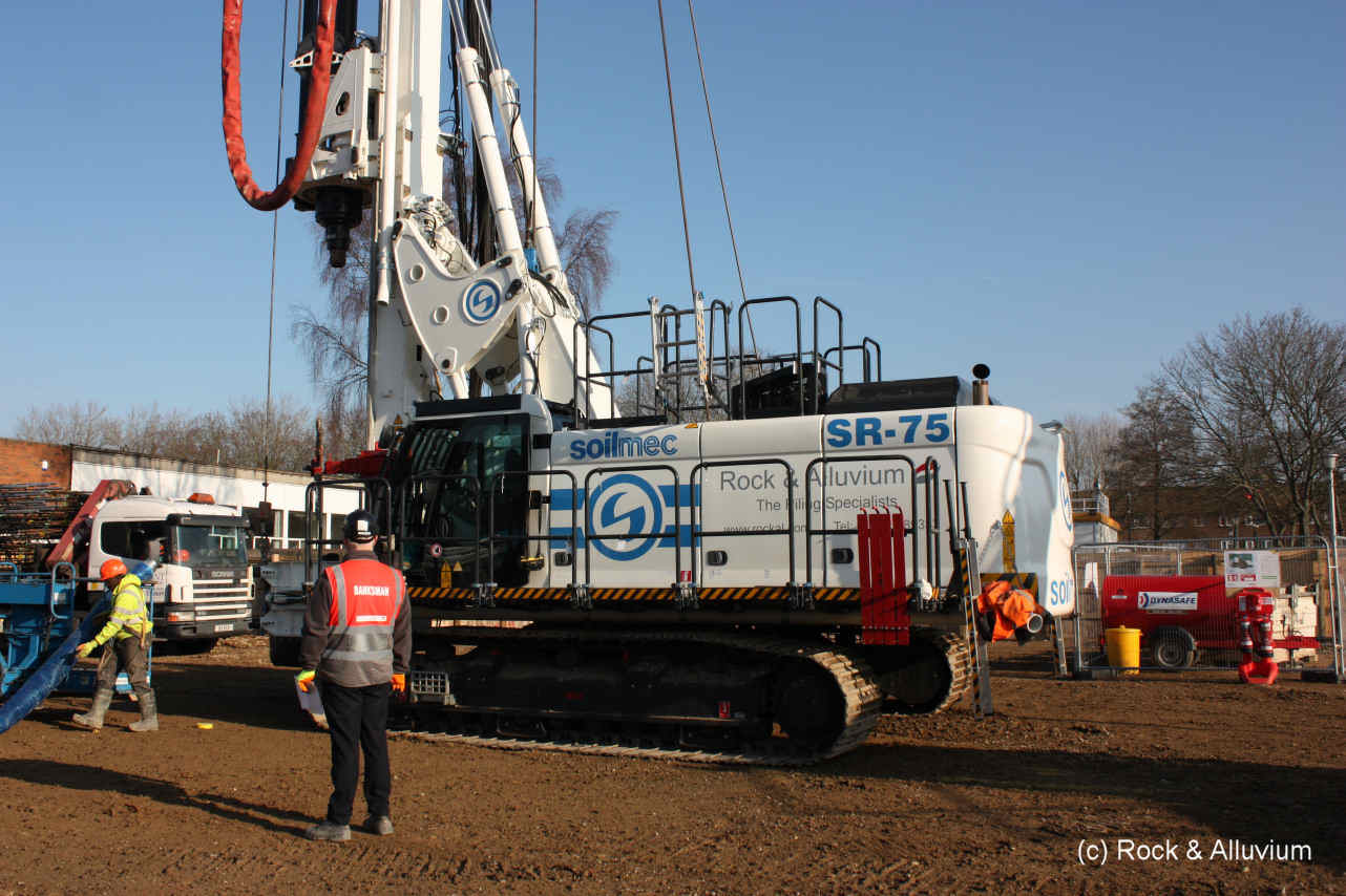
In transit mode, a rig is up to 3.0m wide and 17m long. Once set up ready to work, a rig is up to 4.5m wide, 8.5m long and 30m in height. In addition to the rig, the auxillery equipment and materials are normally delivered on a fleet of articulated and rigid hiab lorries.
A piling rig is taller, wider and longer than most 360 degree excavators and has a variable center of gravity. Rigs are therefore not as manoeuverable as excavators. A large area is required for unloading, setting up and moving a piling rig around a site. Roads should be kept clear of parked vehicles in the vicinity of the site entrance to allow easy access and safe unloading. Any notices or approvals are to be arranged by the Principal Contractor in advance of the rig delivery.
In transit mode, a rig is up to 3.0m wide and 17m long. Once set up ready to work, a rig is up to 4.5m wide, 8.5m long and 30m in height. In addition to the rig, the auxillery equipment and materials are normally delivered on a fleet of articulated and rigid hiab lorries.
Site Setup
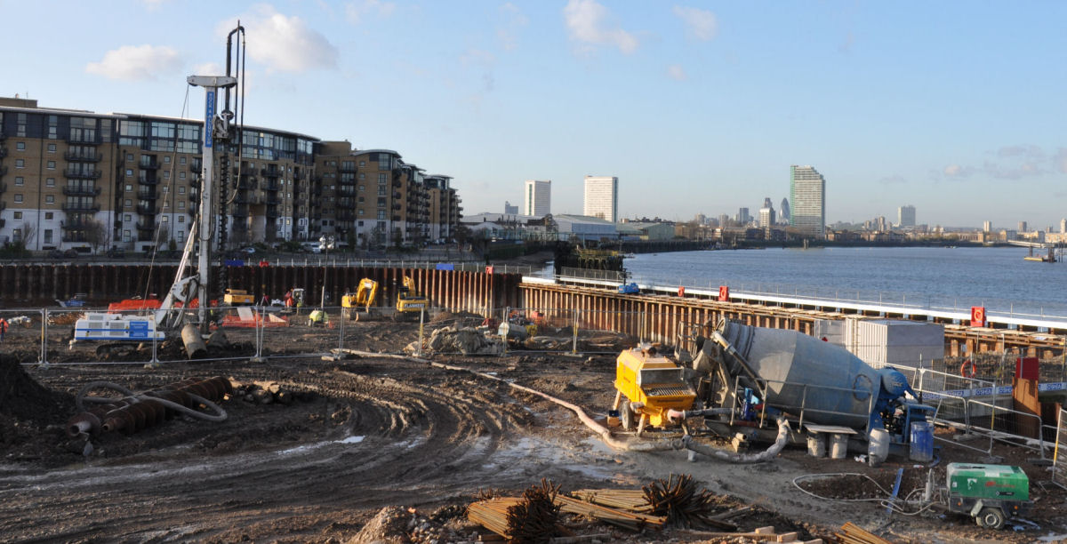 A static agitator is used for storage of ready-mix concrete, up to 20 loads being delivered per day. The concrete is pumped through a reinforced rubber ground hose to the rig (maximum practical pumping distance approx. 100m). Dumpers, excavators and wagons must be prevented from crossing the ground hose as this can lead to catastrophic hose failure.
The space required for the agitator and pump set-up is approximately 4m x 15m, and must have suitable access for ready-mix concrete deliveries. A mains pressure water supply is also required for priming the pump up at the start of the shift and washing out the pump and ground hose at the end of the shift. In addition, an area is required for fabrication and storage of reinforcement cages along with access for a crane.
A static agitator is used for storage of ready-mix concrete, up to 20 loads being delivered per day. The concrete is pumped through a reinforced rubber ground hose to the rig (maximum practical pumping distance approx. 100m). Dumpers, excavators and wagons must be prevented from crossing the ground hose as this can lead to catastrophic hose failure.The space required for the agitator and pump set-up is approximately 4m x 15m, and must have suitable access for ready-mix concrete deliveries. A mains pressure water supply is also required for priming the pump up at the start of the shift and washing out the pump and ground hose at the end of the shift. In addition, an area is required for fabrication and storage of reinforcement cages along with access for a crane.
Working Area
 A site visit may be required to assess suitability of plant and equipment. Particular attention should be paid to neighbouring buildings with roof overhangs. Generally 1m side clearance is required over full height of rig.
Party-wall approvals are normally required and site specific safety procedures must be agreed for works adjacent to railways or tube lines.
A site visit may be required to assess suitability of plant and equipment. Particular attention should be paid to neighbouring buildings with roof overhangs. Generally 1m side clearance is required over full height of rig.Party-wall approvals are normally required and site specific safety procedures must be agreed for works adjacent to railways or tube lines.
Pile Testing
The two common types of pile test are sonic integrity testing and maintained pile load testing.
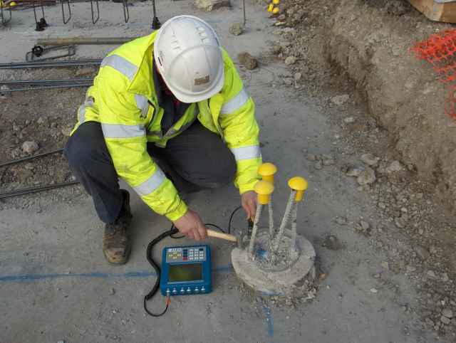 Sonic Integrity Testing
The number of piles to be tested is determined by the contract along with the number of visits. The test is normally carried out once the piles have been trimmed to cut-off level. It should be borne in mind that a minimum of 3 working days notice is required for a test visit.
Pile trimming should not be carried out until the pile has been cast 7 days. Various methods are available along with techniques that facilitate trimming e.g. reinforcement de-bonding. The methods and techniques adopted would vary according to pile size and depth of cut off.
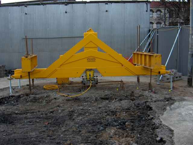 Maintained Load Test
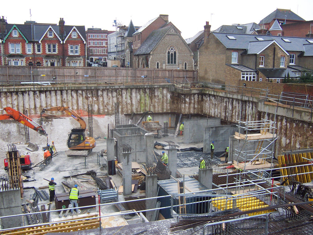
For a maintained load test a steel collar is cast on the pile, and anchor piles are installed around the test pile in a grid arrangement. After installation, the test area must be cordoned off and kept clear of site traffic to prevent damage to the test and anchor piles. The test cannot be carried out until 7 days after installation or when the concrete has reached a minimum strength as specified in the design.
The two common types of pile test are sonic integrity testing and maintained pile load testing.
Sonic Integrity TestingThe number of piles to be tested is determined by the contract along with the number of visits. The test is normally carried out once the piles have been trimmed to cut-off level. It should be borne in mind that a minimum of 3 working days notice is required for a test visit.
Pile trimming should not be carried out until the pile has been cast 7 days. Various methods are available along with techniques that facilitate trimming e.g. reinforcement de-bonding. The methods and techniques adopted would vary according to pile size and depth of cut off.
Maintained Load TestFor a maintained load test a steel collar is cast on the pile, and anchor piles are installed around the test pile in a grid arrangement. After installation, the test area must be cordoned off and kept clear of site traffic to prevent damage to the test and anchor piles. The test cannot be carried out until 7 days after installation or when the concrete has reached a minimum strength as specified in the design.
Environment
Regeneration of inner city areas and brownfield sites has resulted in increased awareness of environmental noise and vibration. In many cases, sites may have a 'Section 60' notice limiting the level of noise at the site boundary. Such environmental considerations can dictate both the type of pile and the size and type of piling equipment that can be used.
Rock & Alluvium offer a range of hydraulically mounted boring rigs that are ideally suited to working in these sensitive areas. Modern, fully computerized piling rigs are used, that have been developed to achieve the high environmental standards expected within today's market place. The further from the piling operation the lower the noise levels. The use of equipment with such a low level of noise has a minimum effect upon noise sensitive areas and the environment generally.
For comparison, noise levels for a driven pile can typically exceed 100dB(A) at source. Consequently where noise is a sensitive issue, bored piling may prove to be a more suitable solution. British Standard BS5228:Part 4:1992 relates to Noise & Vibration Control on Construction and Open Sites and is applicable to piling operations.
With regard to vibration, people are sensitive to vibration and understandably can become concerned if they perceive that damage could be occurring to their property as a result of piling activities. BS7385-2:1993 relates to the evaluation and measurement of vibration for buildings and provides guidance to damage levels from ground borne vibration.
If piling is required in close proximity to existing structures or in particularly sensitive areas (i.e. schools, hospitals, town centres), then it would be prudent to adopt a piling system that can install piles with a minimum of disturbance. Rock and Alluvium have installed CFA piles within 1.0 m of existing housing and other structures and would favour this pile type where noise and vibration is a major consideration.
It is not the intention of this guidance note to provide site-specific details and the scheme designer must consider all features pertinent to the subject site.
Health, Safety, Environment & Quality
Site Geology
 For a cohesive soil, the majority of load will be carried in shaft friction. In reality due to the design factors of safety, it is quite likely that in a cohesive soil the design working load for the pile will be carried almost entirely by shaft friction. Conversely, for a non-cohesive soil, it is likely that the majority of the load will be carried in end bearing. For the end bearing to be mobilised, the pile will 'bed' into the founding material. Where load is carried in shaft friction, the stress within the pile shaft dissipates with pile depth. Thus the elastic shortening of the pile will be less than for a free standing column.
There will however be some pile settlement as the shaft frictional resistance is taken up. Hence for a pile founding in cohesive soils, settlements and recovery for loads up to working load could be expected to be dominated by elastic behaviour. Where load is carried by majority end bearing, the shaft frictional resistance may be less than the piles safe working load. Thus the concrete stress will not dissipate as rapidly - the elastic shortening of the pile may therefore be similar to that for a free standing column. In addition, with all the shaft friction mobilised, pile settlement is greater as the contribution from end bearing is attained. Hence for a pile founding in a cohesionless soil, settlement and recovery will not be dominated by elastic behaviour.
The settlement at working load for a pile in a cohesionless soil could generally be expected to be greater than that of a pile in a cohesive soil. Recovery upon unloading would be expected to be less for the pile in a cohesionless soil. Consequently, when specifying pile performance criteria, it is necessary to have an understanding of how the pile is carrying its load. It is not sensible to have a standard settlement and recovery criteria at working load and 50% overload since this would result in more onerous a criteria for a pile in a cohesionless soil type. It is intended that this guidance note will assist the Engineer in specifying pile performance criteria for various ground conditions in an informed and logical manner whilst also explaining the reasons for the differences in pile settlement behaviour.
For a cohesive soil, the majority of load will be carried in shaft friction. In reality due to the design factors of safety, it is quite likely that in a cohesive soil the design working load for the pile will be carried almost entirely by shaft friction. Conversely, for a non-cohesive soil, it is likely that the majority of the load will be carried in end bearing. For the end bearing to be mobilised, the pile will 'bed' into the founding material. Where load is carried in shaft friction, the stress within the pile shaft dissipates with pile depth. Thus the elastic shortening of the pile will be less than for a free standing column.There will however be some pile settlement as the shaft frictional resistance is taken up. Hence for a pile founding in cohesive soils, settlements and recovery for loads up to working load could be expected to be dominated by elastic behaviour. Where load is carried by majority end bearing, the shaft frictional resistance may be less than the piles safe working load. Thus the concrete stress will not dissipate as rapidly - the elastic shortening of the pile may therefore be similar to that for a free standing column. In addition, with all the shaft friction mobilised, pile settlement is greater as the contribution from end bearing is attained. Hence for a pile founding in a cohesionless soil, settlement and recovery will not be dominated by elastic behaviour.
The settlement at working load for a pile in a cohesionless soil could generally be expected to be greater than that of a pile in a cohesive soil. Recovery upon unloading would be expected to be less for the pile in a cohesionless soil. Consequently, when specifying pile performance criteria, it is necessary to have an understanding of how the pile is carrying its load. It is not sensible to have a standard settlement and recovery criteria at working load and 50% overload since this would result in more onerous a criteria for a pile in a cohesionless soil type. It is intended that this guidance note will assist the Engineer in specifying pile performance criteria for various ground conditions in an informed and logical manner whilst also explaining the reasons for the differences in pile settlement behaviour.
Pile Performance
 The performance of a pile is determined by the following criteria:
| Pile Load: |
The applied load will affect the pile settlement. The greater the load, the larger the settlement. The usual loads designed to are compression, horizontal and tension. |
| Pile Diameter & Length: |
The recorded movement at the pile head will be as a result of both elastic shortening and pile settlement. Elastic shortening will influence pile head deflection to a greater extent in a long slender pile than in a short, large diameter pile. |
| Ground Conditions: |
The ground conditions and method of pile installation, determines the proportion of applied load carried in shaft friction and end bearing. |